
Why Long-Reach ER/ZR Optics Need a Fixed Attenuator on Short Fiber: Receiver Overload Explained
2026-11-12 09:24:35
An ER4 or ZR4 module is bought for distance — 40km, 80km, sometimes 100km. Then it gets installed on a 2km span between two rooms in the same building, the link comes up, and the errors start: CRC errors under load, flapping, receiver-power alarms in the monitoring. The instinct is to blame the fibre, the patch cords, or a faulty module. More often the problem is the opposite of what the symptoms suggest: the link is not too weak. It is too hot.
A long-reach optic on a short span delivers far more light than the far-end receiver is built to take. The fix is not a different module — it is a small, fixed piece of glass that takes a few dB off before the light reaches the receiver. This guide explains why it happens, how to work out whether it is happening on your link, and how to pick the right fixed fiber attenuator for it.
A Receiver Has a Ceiling, Not Just a Floor
Every optical receiver has two limits, and only one of them gets talked about. The familiar one is sensitivity — the weakest signal the receiver can still read, −18.5 dBm on our 100G QSFP28 ER4 and −28 dBm on our 100G QSFP28 ZR4. The one that causes the trouble is the other end of the window: overload, the maximum input power the receiver can take before it saturates. Above that ceiling the receiver cannot tell ones from zeroes cleanly, however good the fibre is.
Long-reach modules are designed to push light through tens of kilometres of fibre and dozens of connectors. Their launch power is high because most of it is expected to be lost on the way — ER4 launches at up to +6.5 dBm, ZR4 at up to +7 dBm. On a 40km or 80km span, that budget is spent. On a 2km span, almost none of it is, and nearly the full launch power arrives at the far end.
Typical figures for the four long-reach classes show how close the ceiling sits to a short link's received power. Exact numbers vary by vendor, so check your own module's datasheet — but the shape of the problem does not change:
| Module | Reach | Detector | Launch power (dBm) | Sensitivity (dBm) | Overload (dBm) |
|---|---|---|---|---|---|
| 40GBASE-ER4 | 40km | APD | −2.7 to +4.5 | −21.2 to −19.5 | −4.5 (some −1.5) |
| 40GBASE-ZR4 | 80km | PIN / SOA+PIN | 0 to +6.0 | −25.0 to −22.0 | −8.0 to −7.0 |
| 100GBASE-ER4 | 40km | APD | −2.5 to +6.5 | −20.5 to −19.0 | −4.5 to −3.5 |
| 100GBASE-ZR4 | 80km | SOA + PIN | +2.0 to +6.5 | −28.0 | −3.5 (some vendors quote +2.0) |
One measurement detail matters before you compare any reading against that ceiling. The launch, sensitivity and overload figures above are per lane, as datasheets state them. A power meter on the fibre port reads all four lanes together — about 6 dB more than the per-lane figure. The DDM diagnostics in the switch (display transceiver diagnosis, or your platform's equivalent) report per lane, so compare DDM readings against the ceiling directly; if you measure with a meter, allow for the 6 dB before concluding anything.
And one field rule follows from the table: never connect an ER4 or ZR4 back-to-back over a short span without a pad. On lab links, loopback tests and any span under about 10km, fit a fixed attenuator in front of the receiver as a matter of course. Sustained overload does not just corrupt data — it can damage the APD or SOA receiver it lands on.
The symptoms of overload are easy to misread. The link usually comes up, passes a quick ping test, and then degrades under real traffic: rising CRC and FEC-corrected error counts, intermittent flaps, and a received-power reading in DDM that sits far above the rest of your links. If the DDM receive power on an ER or ZR link is close to the module's launch power rather than tens of dB below it, you are looking at overload, not a weak signal — and no amount of re-seating connectors will fix it.
The Maths on a Short ER4 Link
Take a real example from our own specification tables. A 100G QSFP28 ER4 transmits at up to +6.5 dBm. Put it on a 2km single-mode span: the fibre itself loses about 0.4 dB per kilometre at 1310nm, and two mated connector pairs lose roughly 0.5 dB each. Total link loss is about 1.8 dB, so the far-end receiver sees roughly +4.7 dBm — only 1.8 dB below the maximum launch power, and more than 23 dB above the −18.5 dBm sensitivity floor. The link is not starved for light. It is flooded with it.
The ZR4 is the same story with a wider gap: up to +7 dBm launch against a −28 dBm sensitivity floor means a 35 dB receive window, and on a short span the received power lands near the top of it. Even the 10km LR4, at up to +4.5 dBm launch, runs hot on a very short span. The distance rating on the box is a maximum, not a recommendation — a module rated for 40km is not "better" on a 2km link, it is simply the wrong tool for that distance.
Before reaching for a fix, measure. The DDM reading on the receiving module shows the actual received power; an optical power meter on the receive strand says the same thing. Compare that number with the module's overload (maximum receive power) figure in its datasheet. If the measured power is above the overload figure — or within a dB or two of it — the link needs attenuation, not a new module.
How a Fixed Attenuator Fixes It
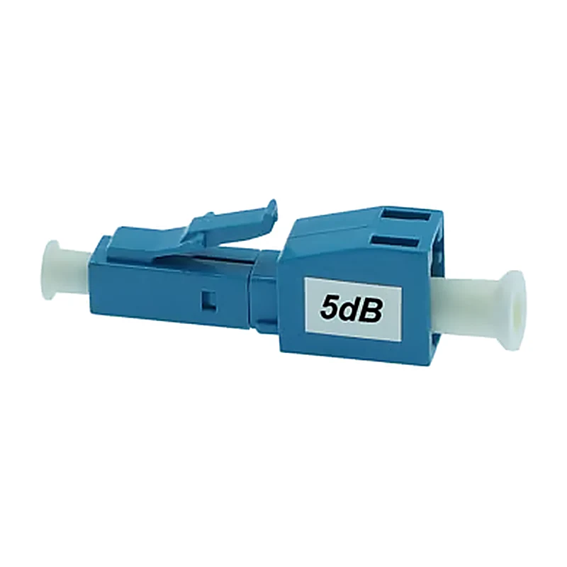
A fixed attenuator is a plug-style device that sits in line on the receive strand, at the receiver end, and removes a fixed amount of power before the light reaches the receiver. It has no dial, no power supply and nothing to drift: the value is built in at the factory with ±0.5 dB tolerance, so a 5 dB pad is a 5 dB pad for the life of the link.
Run the ER4 example through it. Received power without a pad is about +4.7 dBm, and the target is the middle of the receiver's window — around −10 to −15 dBm, well below the overload ceiling and still comfortably above the −18.5 dBm sensitivity floor. Work backwards from the measurement: a 5 dB pad only reaches about −0.3 dBm, which is still above the ER4 ceiling — the link stays overloaded. A 10 dB pad reaches about −5.3 dBm: under the ceiling, but within roughly 2 dB of it, leaving little room for pad tolerance or a hotter-than-typical launch. A 15 dB pad lands at about −10 dBm, squarely in the target zone — which is why short ER/ZR links and lab setups typically need 15–20 dB of padding, not the 5 or 10 dB that a longer span might. Fixed pads also add up in series: a 10 dB and a 5 dB plugged in line give 15 dB, and two 10 dB pads give 20 dB, so the standard stocked values cover the range these links need. Which total to use is a measurement decision, not a guess: read the received power, subtract the pad value, and check the result sits in the middle of the receiver's window rather than near either edge.
Sate's fixed attenuators cover the wavelengths these links actually use: the 1260–1650nm window covers 1310nm ER/ZR optics and 1550nm optics alike. They come in LC/UPC at 5 dB and 10 dB, and SC/UPC at 5 dB, and can be combined in series as described above when a short ER/ZR link needs 15–20 dB; the first choice is which connector matches the port and patch cord on the receive side. Installation takes seconds — unplug the receive strand, plug the pad into the receiver port, reconnect the strand to the pad — and the DDM reading confirms the new level immediately.
Picking the Right Pad: Four Checks
| Check | What to do |
|---|---|
| Measure first | Read the DDM receive power (or a power meter) before choosing. Pick the pad value that lands the result mid-window, not at either edge. |
| Match the connector | LC ports take the LC/UPC pad, SC ports the SC/UPC pad. The pad must match the port and the patch cord on the receive strand. |
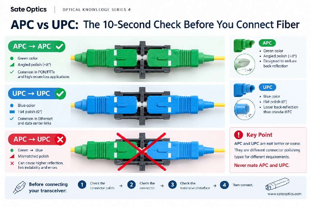
| Match the polish | These are UPC pads for UPC plant. Do not mix UPC and APC connectors — the polish mismatch costs return loss and can damage the ferrule. |
| Check the wavelength | The 1260–1650nm window covers 1310nm and 1550nm single-mode links. It does not cover 850nm multimode — do not put these pads on SR short-reach multimode links. |
When an Attenuator Is the Wrong Answer
An attenuator is the right fix for a link that already exists. It is not the right way to buy a new one. If you are ordering optics for a 2km span, buy the optic rated for that distance — a 10km LR4, or a 2km CWDM4 — instead of an ER4 plus a pad. The shorter-reach module costs less, launches less power, and removes a component from the link.
An attenuator also cannot fix a link that is genuinely lossy. If the received power is already near the sensitivity floor, adding loss makes it worse; that link needs cleaning, re-termination, or a longer-reach module, not a pad. And for lab work where the loss needs to change between tests, a variable attenuator is the right instrument — a fixed pad is for production links whose loss budget is known and stable.
The common case where the pad earns its place is the one this article started with: long-reach spares standardised across a network, a metro optic reused on a campus span, or a link that was re-patched to a shorter path after a move. The module is already bought and already installed. A small passive part is a better answer than a module swap.
Four Mistakes That Keep the Errors Coming
- Buying ER "to be safe" on a short link. Reach is not headroom. A 40km module on a 2km span is overpowered, not safe — match the optic to the measured distance, and keep ER/ZR for spans that actually need the budget.
- Guessing the pad value instead of measuring. A 5 dB pad on a link that needs 15 dB leaves the receiver still overloaded, and the errors continue. One DDM reading before ordering settles it.
- Putting the pad on the wrong strand or the wrong end. The pad belongs on the receive strand, at the receiver end, so the DDM reading on that module shows the padded level. A pad on the transmit strand attenuates the same light, but you lose the clean before-and-after reading at the receiver.
- Using a 1310/1550nm pad on an 850nm multimode link. The 1260–1650nm window does not cover SR optics. A pad that is out of its wavelength window does not attenuate predictably — and a short multimode link rarely needs one, since SR launch power is already low.
Before You Order
Every Sate Optics 100G QSFP28 module is coded for major networking platforms — including Cisco, Juniper, Arista, Huawei, Nokia, H3C and ZTE — and 100% tested before shipment, and every one is covered by a 3-year warranty with lifetime maintenance. The fixed attenuators are accessories: covered by a 1-year warranty, with a standard lead time of 3–7 days for most products (large-quantity orders typically take 10–30 days), and samples are available for evaluation.
If a long-reach link is erroring on a short span, send us the switch models, the module part numbers at both ends, and the DDM receive-power reading. We will confirm whether the link is overloaded, which pad value lands it mid-window, and the connector type you need — before you order. It is much cheaper than returning the wrong reach.
Need Help Choosing the Right Module?
Tell us your switch model and the distance you need to cover — we confirm compatibility and reply within 24 hours.
Get a Quote Chat on WhatsAppPrevious:100G QSFP28 for Spine-Leaf Networks: Choosing SR4, CWDM4, LR4, DAC and AOC by Link Tier
Next:No More