
Optical Transceiver Troubleshooting: 5 Checks for Reliable Network Links
2026-08-10 21:20:22
The Transceiver Wasn’t Always the Problem: 5 Checks for a More Reliable Optical Link
A practical guide to troubleshooting intermittent optical link issues before replacing an SFP, SFP+, SFP28, QSFP28, or QSFP-DD transceiver
An optical link can look simple from the outside: two switches, two transceivers, and a fiber patch cord.
But when a link starts flapping or unexpectedly goes down, the root cause is not always the optical transceiver itself.
We recently worked with a customer experiencing intermittent interruptions on an optical connection. The switch configuration appeared normal, and the link could come back online after a short interruption. Instead of immediately assuming that the transceiver was defective, we looked at the entire optical link.
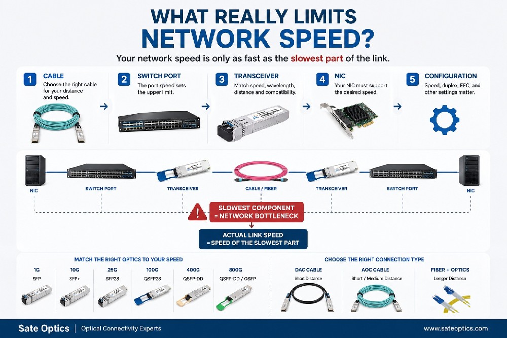
This approach matters because optical reliability depends on several factors working together:
Transceiver + Switch + Fiber + Distance + Optical Power + Compatibility
In this article, we explain five practical checks that network engineers can use when troubleshooting an unstable optical connection.
1. Check Transceiver and Switch Compatibility
The first step is to confirm that the optical transceiver is appropriate for the network equipment and port.
A module may have the correct speed and connector but still require verification against the switch, NIC, router, or other host device.
For example, common transceiver categories include:
1G SFP
10G SFP+
25G SFP28
40G QSFP+
100G QSFP28
400G QSFP-DD
800G high-speed optical transceivers
When troubleshooting compatibility, check:
Host or switch model
Port type
Supported interface
Data rate
Transceiver coding or compatibility requirements
Wavelength
Fiber type
Transmission distance
Vendor-specific requirements
Common model keywords that network engineers may encounter include:
Cisco GLC-SX-MMD, Cisco GLC-LH-SMD, Cisco GLC-ZX-SMD, Cisco SFP-10G-SR, Cisco SFP-10G-LR, Cisco SFP-25G-SR-S, Cisco QSFP-100G-SR4-S, Cisco QSFP-100G-LR4-S, QSFP-DD 400G DR4, QSFP-DD 400G FR4, and QSFP-DD 400G LR4.
These model families have different optical specifications and application requirements. A model number alone should never be treated as sufficient proof of compatibility. The actual host equipment, port, firmware or coding requirements, fiber infrastructure, and link distance should also be verified.
Practical tip
Before ordering replacement optics, provide the supplier with the exact equipment model and port information, rather than only saying “I need a 10G module.”
That small difference can prevent a lot of troubleshooting later.
2. Verify Wavelength and Fiber Type
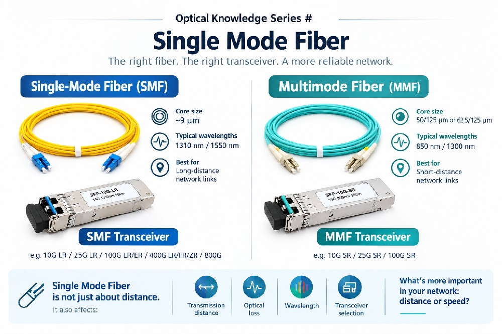
The optical wavelength needs to match the intended fiber application.
Typical wavelengths used in Ethernet optical transceivers include:
850 nm — commonly associated with multimode fiber applications
1310 nm — widely used for single-mode fiber applications
1550 nm — commonly used for longer-distance single-mode applications and certain DWDM/CWDM solutions
Fiber type is equally important.
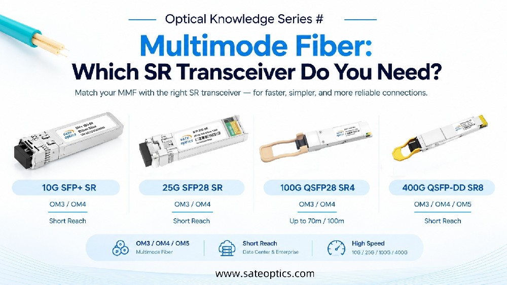
Multimode Fiber — MMF
Multimode fiber is commonly used for shorter-distance data center and enterprise connections.
Typical optical technologies include:
850 nm SR optics
LC or MPO/MTP connectivity depending on the application
Short-distance 10G, 25G, 40G, and 100G links
Single-Mode Fiber — SMF
Single-mode fiber is commonly used for longer-distance connections.
Typical applications include:
1310 nm LR optics
1550 nm extended-distance optics
CWDM/DWDM systems
ISP and telecom networks
Data center interconnects
The important point is:
Do not select an optical transceiver based only on data rate.
A 10G module is not simply “a 10G module.” The wavelength, fiber type, connector, distance, and optical specifications all matter.
3. Check Transmission Distance and Optical Budget
Transmission distance is another common source of optical link problems.
For example, a short-range SR transceiver should not simply be substituted for a long-range LR transceiver because both operate at the same data rate.
The optical link should be evaluated against the module's specified transmission distance and optical budget.
The basic concept is:
Optical Power Budget ≈ Transmitter Output Power − Receiver Sensitivity
The available optical budget needs to be sufficient for the total loss of the link, including factors such as:
Fiber attenuation
Connector loss
Splice loss
Patch panels
Additional passive components
Aging and engineering margin
A link that is close to the optical limits may be more sensitive to additional loss.
This is particularly important for:
Long-distance enterprise links
ISP networks
Telecom networks
Data center interconnects
DWDM/CWDM deployments
40 km, 80 km, and other extended-distance applications
Important reminder
“The module supports 20 km” does not automatically mean every 20 km fiber link will work perfectly.
The complete link budget still needs to be considered.
4. Check Tx and Rx Optical Power
If the transceiver supports DOM/DDM (Digital Optical Monitoring / Digital Diagnostic Monitoring), optical parameters can provide valuable information during troubleshooting.
Depending on the module and host platform, engineers may be able to monitor parameters such as:
Temperature
Supply voltage
Tx optical power
Rx optical power
Laser bias current
Why is Rx power important?
A link can remain operational even when the optical margin is becoming smaller.
Monitoring the optical power can therefore help identify potential issues before they become complete link failures.
For example, an engineer may compare the observed Rx power against:
The transceiver's specified receiver range
Receiver sensitivity
Expected optical loss
Historical readings from the same link
However, DOM/DDM values should be interpreted in context.
A single reading should not automatically be treated as proof that a transceiver is defective.
Changes in fiber condition, connector contamination, temperature, patching, or other parts of the optical path can also affect the readings.
5. Inspect Fiber, Connectors, and Polarity
Sometimes the transceiver gets replaced when the real problem is somewhere else in the optical path.
Before replacing a module, check:
Fiber
Look for:
Excessive bending
Micro-bends
Damaged patch cords
Incorrect fiber type
Excessive insertion loss
Connectors
Check for:
Dust or contamination
Scratches
Physical damage
Poor connection
Even a small amount of contamination on an optical connector can affect optical performance.
Polarity
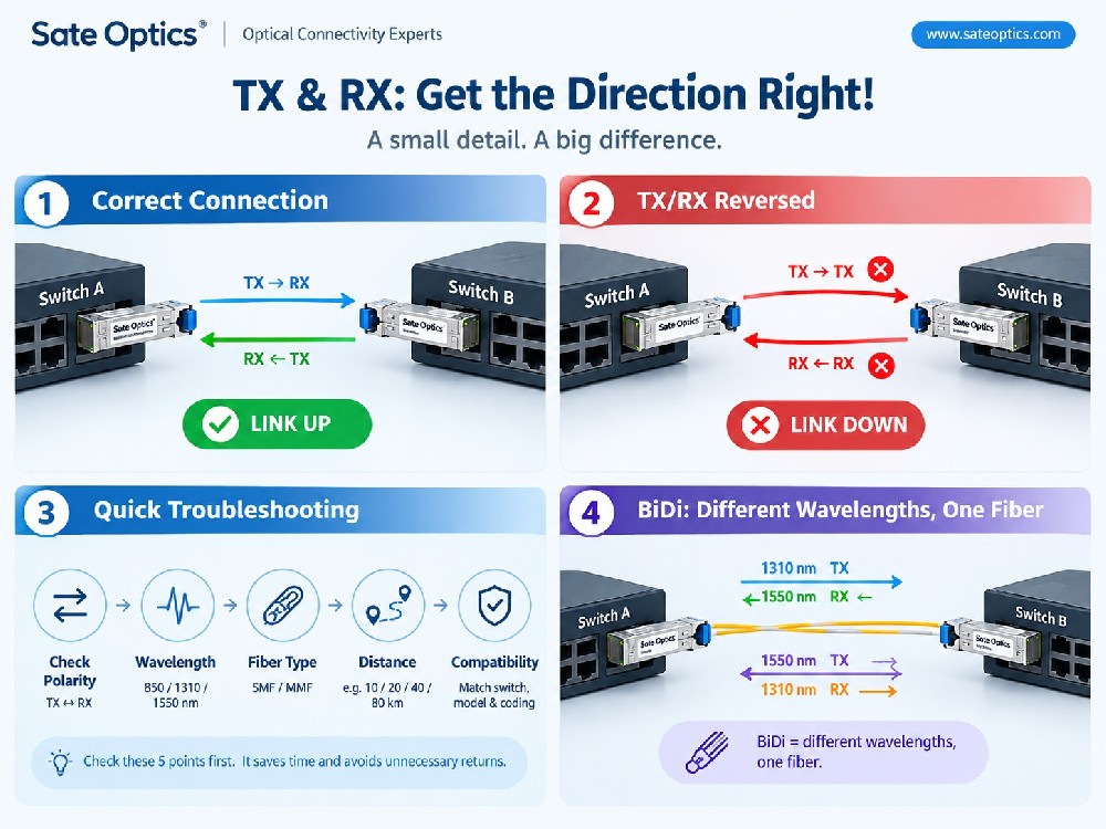
For duplex fiber connections, make sure the transmit and receive paths are correctly connected.
For parallel-optics applications using MPO/MTP, polarity and fiber mapping become especially important.
This is particularly relevant to high-speed transceivers such as:
40G QSFP+
100G QSFP28 SR4
100G QSFP28 PSM4
400G QSFP-DD DR4
400G QSFP-DD FR4
Other parallel or breakout optical configurations
What We Learned from the Customer Case
The most important lesson from this type of troubleshooting is simple:
Do not troubleshoot the transceiver in isolation. Troubleshoot the entire optical link.
When a customer reports intermittent link problems, the correct process is not simply:
“Replace the SFP.”
A better approach is:
1. Identify the host equipment and port
↓
2. Verify transceiver compatibility
↓
3. Check wavelength and fiber type
↓
4. Confirm transmission distance and optical budget
↓
5. Check Tx/Rx optical power
↓
6. Inspect fiber, connectors, and polarity
↓
7. Replace the transceiver only when the evidence points to the module
This process helps distinguish between a genuine transceiver issue and a problem somewhere else in the optical path.
Application Scenarios
These troubleshooting principles are useful across several network environments.
Data Centers
Data centers often use high-density optical connections such as:
10G SFP+
25G SFP28
100G QSFP28
400G QSFP-DD
With increasing port speeds, fiber type, connector quality, optical power, and compatibility become increasingly important.
Enterprise Networks
Enterprise networks may combine 1G, 10G, and 25G connections across different generations of switches.
Correct compatibility and fiber selection can help simplify upgrades without unnecessarily replacing the entire infrastructure.
ISP and Telecom Networks
Longer optical links require greater attention to:
Transmission distance
Optical budget
Receiver sensitivity
Optical power
Fiber loss
CWDM/DWDM architecture
For these environments, selecting a transceiver based only on speed is not enough.
Data Center Interconnects
DCI applications can involve 100G, 400G, and higher-speed optical technologies.
Before deployment, engineers should verify the complete optical path and ensure that the selected transceiver matches the equipment, fiber infrastructure, distance, and required optical performance.
Network Upgrades and Replacement Projects
When replacing OEM optics with compatible alternatives, testing should include:
Host compatibility
Link establishment
DOM/DDM readings where available
Optical power
Traffic stability
Fiber infrastructure
This is especially useful when upgrading an existing network while keeping the current switching infrastructure.
Common Optical Transceiver Models and Keywords
When researching replacement or compatible optics, network engineers may encounter model numbers such as:
1G SFP
Cisco GLC-SX-MMD
Cisco GLC-LH-SMD
Cisco GLC-ZX-SMD
10G SFP+
Cisco SFP-10G-SR
Cisco SFP-10G-LR
Cisco SFP-10G-ER
25G SFP28
Cisco SFP-25G-SR-S
Cisco SFP-25G-LR-S
100G QSFP28
Cisco QSFP-100G-SR4-S
Cisco QSFP-100G-LR4-S
Cisco QSFP-100G-ER4-S
400G QSFP-DD
400G QSFP-DD DR4
400G QSFP-DD FR4
400G QSFP-DD LR4
These keywords represent different optical solutions rather than interchangeable products. Always verify the specific equipment and application requirements before selecting a replacement.
How Sate Optics Approaches Optical Compatibility
At Sate Optics, we believe that selecting an optical transceiver should start with the network requirement, not simply the product name.
Our approach is to verify key parameters such as:
✓ Host equipment and port
✓ Data rate
✓ Wavelength
✓ Fiber type
✓ Connector
✓ Transmission distance
✓ Optical budget
✓ Compatibility requirements
✓ DOM/DDM parameters where applicable
Each compatible optical module can then be matched to the intended application and tested before shipment.
Our optical transceiver portfolio covers applications from 1G to 800G, including SFP, SFP+, SFP28, QSFP+, QSFP28, QSFP-DD, DAC, AOC, CWDM, DWDM, and other optical networking solutions.
FAQ
1. Can an optical transceiver cause an intermittent link problem?
Yes. A transceiver can be one possible cause of an unstable optical link, but it should not automatically be assumed to be the root cause. Compatibility, optical power, fiber, connectors, distance, and environmental conditions should also be checked.
2. How do I troubleshoot an SFP or SFP+ link that keeps going down?
Start by checking the switch port and transceiver compatibility, then verify wavelength, fiber type, link distance, optical power, connectors, and fiber condition. If DOM/DDM is available, compare the optical readings with the module's specified operating range.
3. What is DOM/DDM on an optical transceiver?
DOM, commonly called Digital Optical Monitoring, allows supported equipment to monitor optical and electrical parameters such as temperature, voltage, Tx power, Rx power, and laser bias current. The exact monitored parameters depend on the transceiver and host platform.
4. Does a higher-power optical module always provide a more reliable link?
No. Higher optical power does not automatically mean better reliability. The transmitter output, receiver sensitivity, optical budget, and the specifications of the complete link all need to be considered.
5. What is the difference between SR and LR transceivers?
SR and LR generally refer to different reach categories and optical implementations. SR optics are commonly associated with shorter-distance multimode applications, while LR optics are commonly used for longer-distance single-mode connections. Always check the specific manufacturer's specifications for the exact module.
6. Can I replace an OEM optical transceiver with a compatible module?
In many network environments, compatible optics can be used, but compatibility should be verified against the exact host equipment, port, firmware or coding requirements, and optical specifications. Testing before large-scale deployment is recommended.
7. What information should I provide when asking for a compatible optical module?
The most useful information includes the switch/router/server model, port type, required data rate, transmission distance, fiber type, connector type, and original transceiver part number.
The more complete the information, the easier it is to identify the appropriate optical solution.
Final Takeaway
A stable optical link is rarely the result of one component alone.
It comes from the right combination of:
Transceiver + Switch + Fiber + Distance + Optical Power + Compatibility
So the next time an optical link starts flapping, don't immediately blame the SFP.
Troubleshoot the entire optical link first.
That approach can save troubleshooting time, reduce unnecessary replacements, and help build a more reliable network.
Need Help Selecting a Compatible Optical Transceiver?
If you are replacing OEM optics, troubleshooting an unstable link, or planning a network upgrade, send us the equipment model, original transceiver part number, speed, fiber type, and transmission distance.
Our team can help check the optical specifications and identify a suitable compatible solution for your application.
Contact Sate Optics for optical transceiver compatibility and network connectivity solutions from 1G to 800G.
[Website: www.sateoptics.com]
Previous:Link Budget Explained: Why 40km SFP Can Fail at 20km | Optical Transceiver Guide
Next:Data Center Copper vs Fiber: RJ45, DAC, AOC & Optical Transceivers