
SFP Insertion Loss & Link Loss: Optical Power Guide
2026-10-08 20:57:02
SFP Insertion Loss and Link Loss: How to Check Optical Power Before a Link Fails
A fiber link can be within the rated distance of an SFP and still experience low Rx power, link instability, or even a link failure.
The reason is simple: distance is only one part of the optical link budget.
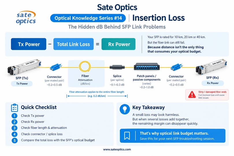
Fiber attenuation, connector loss, splice loss, patch panels, and other passive components all consume optical power between the transmitting SFP and receiving SFP.
Understanding insertion loss and total link loss can help network engineers select the right optical transceiver and troubleshoot problems before they become outages.
What Is Insertion Loss in an SFP Link?
Insertion loss is the reduction in optical power caused by introducing a component into an optical path.
In a real SFP link, the total optical loss can come from several sources:
Fiber attenuation
Connector loss
Splice loss
Patch panels and other passive components
Other optical components in the link
Fiber attenuation is normally expressed in dB/km, while connector and splice losses are expressed in dB per connection or splice.
It is important not to treat fiber attenuation as a single loss point near the transmitter. Fiber attenuation occurs along the entire fiber length.
Why Can an SFP Fail Even When the Distance Is Within Its Rated Reach?
An SFP's rated reach does not mean that every link within that distance will have the same optical loss.
For example, two 10 km links may have very different loss characteristics.
One may have:
A short, clean fiber path
Few connectors
No unnecessary splices
Another may have:
Multiple patch panels
Several connector pairs
Additional splices
Higher fiber attenuation
Dirty or damaged fiber endfaces
The second link can consume significantly more of the available optical budget even though both links are the same length.
Juniper's transceiver planning documentation similarly treats fiber attenuation, connectors, splices, and other losses as part of the link-loss calculation and recommends checking the available power margin.
How Do You Calculate SFP Optical Power Budget?
A basic optical power budget can be expressed as:
Power Budget = Minimum Tx Power − Receiver Sensitivity
For example, if a transceiver has:
Minimum Tx power: −3 dBm
Receiver sensitivity: −14 dBm
Then:
Power Budget = −3 − (−14) = 11 dB
This means the optical link has approximately 11 dB of available loss under the stated worst-case specifications.
The actual link then needs to stay within that budget.
How Do You Calculate Total SFP Link Loss?
A simplified calculation is:
Total Link Loss = Fiber Loss + Connector Loss + Splice Loss + Other Passive Losses
Fiber loss can be estimated as:
Fiber Loss = Fiber Length × Fiber Attenuation
For example, if a fiber path is 10 km and the applicable attenuation is 0.35 dB/km:
10 km × 0.35 dB/km = 3.5 dB
Connector and splice losses must then be added according to the actual installation and component specifications.
The exact values should always come from the applicable fiber, connector, splice, passive-component, and transceiver specifications rather than from a universal assumed number.
What Is Optical Power Margin?
After determining the transceiver's available power budget and the expected link loss, the remaining margin is important.
Power Margin = Power Budget − Total Link Loss
A positive margin means the calculated link loss is within the available power budget. A very small margin, however, leaves less room for additional losses or changes in the installed link.
For this reason, optical link design should not simply ask:
“Is the distance within the SFP's rated reach?”
A better question is:
“Does the complete optical path stay within the transceiver's optical budget?”
This distinction is especially important for longer-reach and higher-speed optical transceivers.
What Causes High Optical Loss in an SFP Link?
When Rx power is lower than expected, check the entire optical path rather than replacing the SFP immediately.
1. Fiber attenuation
Longer fiber produces more attenuation. The applicable attenuation depends on the fiber type, wavelength, and operating conditions.
2. Connector loss
Every mated connector pair can introduce additional loss. Multiple patch panels and cross-connects can therefore consume a meaningful part of the optical budget.
3. Splice loss
Poor or excessive splices can increase total link loss.
4. Dirty or damaged fiber endfaces
Contamination on a connector endface can increase optical loss and cause unstable links. Fiber inspection and cleaning should be part of normal troubleshooting practice.
5. Passive components
Patch panels, splitters, adapters, and other passive components can add loss that is easy to overlook during an initial distance calculation.
How to Troubleshoot Low SFP Rx Power
If an SFP link is unstable or the reported Rx power is unexpectedly low, a practical troubleshooting sequence is:
1. Check Tx power
Confirm that the transmitting module is operating within its specified optical output range.
2. Check Rx power
Compare the measured or DOM-reported Rx power with the receiver's specified operating range.
3. Check fiber length and type
Confirm the fiber type, wavelength, and actual link distance.
4. Check connectors and fiber endfaces
Inspect, clean, and reconnect the optical interfaces where appropriate.
5. Check splices and passive components
Identify every additional loss point in the optical path.
6. Compare total link loss with the optical budget
The goal is not simply to find a longer-reach SFP. The complete optical path needs to match the transceiver's specifications.
What Should Buyers Check When Choosing an SFP?
When purchasing an optical transceiver, reach is important, but it should not be the only specification you compare.
Check:
Fiber type: SMF or MMF
Wavelength
Transmission distance
Minimum and maximum Tx power
Receiver sensitivity
Maximum receiver input power
Optical power budget
DOM/DDM support
Connector type
Device compatibility
Operating temperature
Coding and testing requirements
For compatible SFPs, device compatibility and coding are also important. A transceiver should be specified and tested for the target platform rather than selected only by speed and reach.
Sate Optics: Compatible SFPs for Different Network Platforms
Sate Optics supplies compatible optical transceivers for a range of network platforms, with options covering common Ethernet speeds and transmission distances.
Compatible modules can be coded and tested for the target device before shipment. This helps customers verify compatibility while keeping the focus on the complete optical link—not just the module itself.
For network upgrades, replacement projects, and repeat deployments, matching the transceiver specifications with the actual fiber infrastructure is essential for consistent link performance.
FAQ
Does a longer SFP reach always mean more optical power?
Not necessarily. Reach, Tx power, receiver sensitivity, optical budget, and other specifications all need to be considered together.
Can a short fiber link cause an SFP to fail?
Yes. A short link can still have excessive loss from connectors, splices, passive components, or other installation issues. For some long-reach modules, the opposite problem can also occur: the received optical power may be too high and require attention to the specified maximum receiver input.
Is insertion loss the same as fiber attenuation?
No. Fiber attenuation describes the reduction in optical power along the fiber, typically expressed in dB/km. Insertion loss generally refers to the loss introduced by inserting a component into an optical path. In a complete link calculation, these losses may all contribute to the total link loss.
What should I check first when SFP Rx power is low?
Start with the complete optical path: Tx power, Rx power, fiber length and attenuation, connector condition, splices, and passive components. Then compare the resulting loss with the transceiver's optical budget.
Final Takeaway
An SFP's rated distance is not the whole story.
A reliable optical link depends on the relationship between:
Tx Power → Total Link Loss → Rx Power
Fiber attenuation, connectors, splices, and passive components all consume optical margin.
Before replacing an SFP, check where the optical power is being lost.
And when selecting a new transceiver, look beyond “10 km / 20 km / 40 km.”
Check the complete optical specification and make sure it matches the actual fiber link.
Need help matching a compatible SFP to your network equipment or optical link?
Contact Sate Optics with your device model, speed, wavelength, fiber type, and required reach.